首頁| 新聞| 娛樂| 游戲| 科普| 文學| 編程| 系統| 數據庫| 建站| 學院| 產品| 網管| 維修| 辦公| 熱點
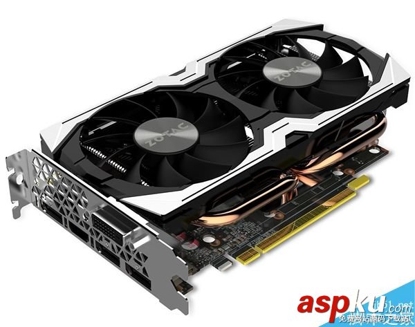
索泰發布一款GTX 1070 Mini迷
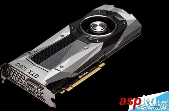
AMD新旗艦顯卡輕松干翻NVIDIA
索泰發布一款GTX 1070 Mini迷你版本:小機
芭蕾舞蹈表演,真實美到極致
下午茶時間,悠然自得的休憩
充斥這繁華奢靡氣息的城市迪拜風景圖片
從山間到田野再到大海美麗的自然風景圖片
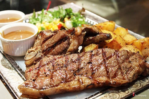
肉食主義者的最愛美食烤肉圖片
夏日甜心草莓美食圖片
人逢知己千杯少,喝酒搞笑圖集
搞笑試卷,學生惡搞答題
新聞熱點
疑難解答
圖片精選
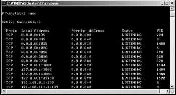
尋找另一半—快速確定特定端口的使
ADSL Modem之IP端口的設定及應用
基于軟交換實現的號碼識別類業務技
軟交換呼叫模型的研究與設計
網友關注